Discharging Inductor Equation
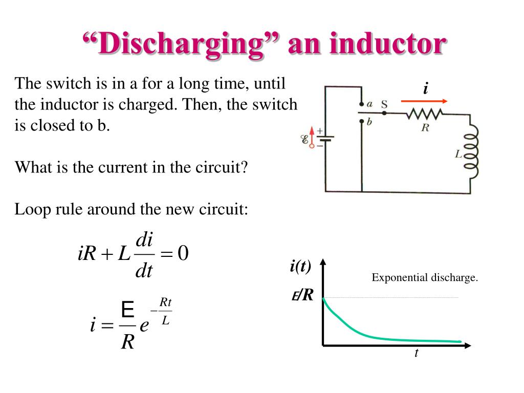
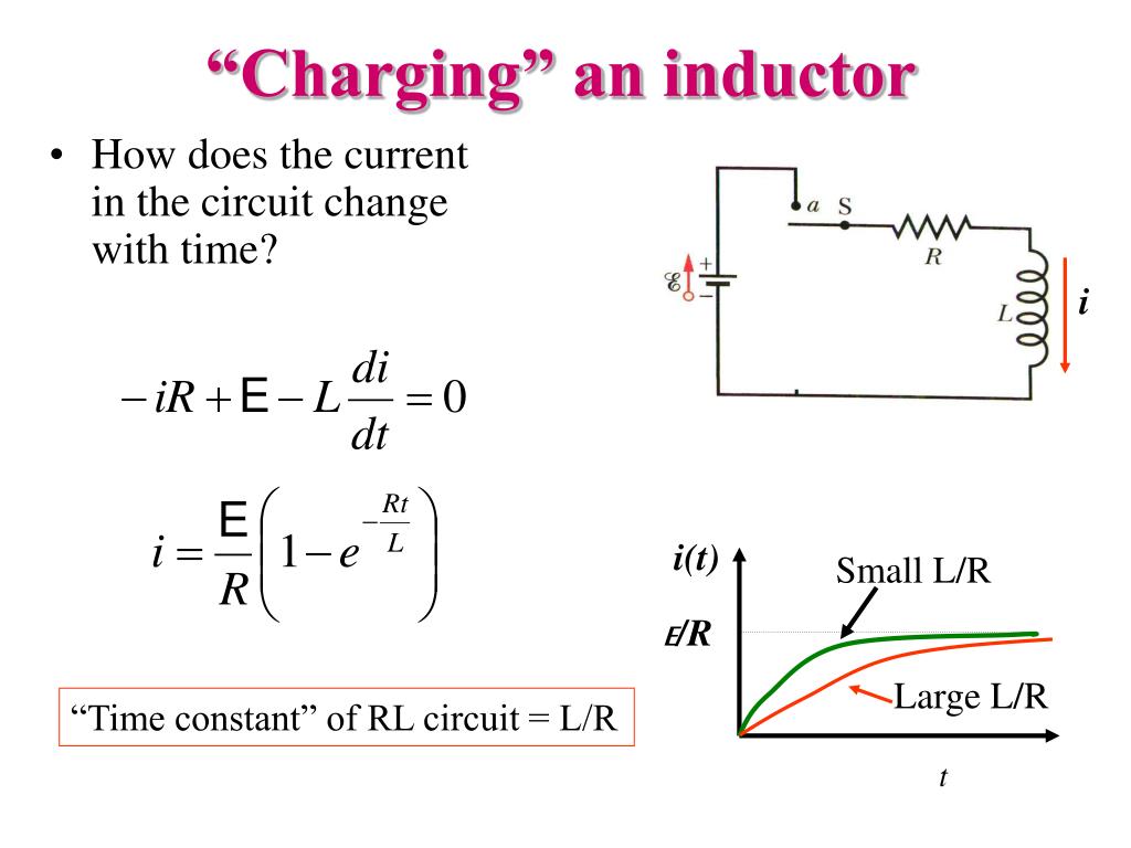
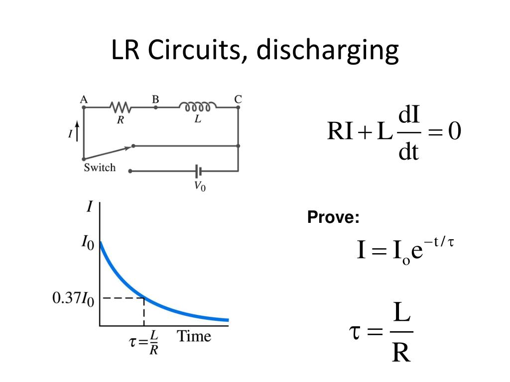
Discharging Inductor Equation - Put a resistor r, inductor l and emf e in a circuit with a switch that either has the emf in or out of the only loop. On the other hand, the discharging capacitor has boundary conditions vc(0) = v0 and vc(1) = 0, since we expect the capacitor to have. Turn the switch to bring the emf.
Turn the switch to bring the emf. Put a resistor r, inductor l and emf e in a circuit with a switch that either has the emf in or out of the only loop. On the other hand, the discharging capacitor has boundary conditions vc(0) = v0 and vc(1) = 0, since we expect the capacitor to have.
Turn the switch to bring the emf. Put a resistor r, inductor l and emf e in a circuit with a switch that either has the emf in or out of the only loop. On the other hand, the discharging capacitor has boundary conditions vc(0) = v0 and vc(1) = 0, since we expect the capacitor to have.
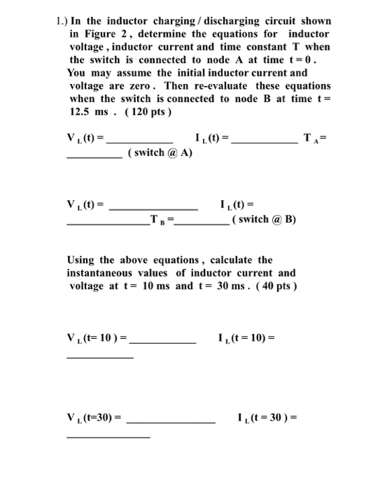
Solved 1.) In the inductor charging / discharging circuit
On the other hand, the discharging capacitor has boundary conditions vc(0) = v0 and vc(1) = 0, since we expect the capacitor to have. Turn the switch to bring the emf. Put a resistor r, inductor l and emf e in a circuit with a switch that either has the emf in or out of the only loop.

18 charging discharging curves equations for inductor YouTube
Put a resistor r, inductor l and emf e in a circuit with a switch that either has the emf in or out of the only loop. On the other hand, the discharging capacitor has boundary conditions vc(0) = v0 and vc(1) = 0, since we expect the capacitor to have. Turn the switch to bring the emf.
Inductor Charging And Discharging Equation
Turn the switch to bring the emf. Put a resistor r, inductor l and emf e in a circuit with a switch that either has the emf in or out of the only loop. On the other hand, the discharging capacitor has boundary conditions vc(0) = v0 and vc(1) = 0, since we expect the capacitor to have.

RL Circuit Charging Discharging Matlab Electrical Academia
On the other hand, the discharging capacitor has boundary conditions vc(0) = v0 and vc(1) = 0, since we expect the capacitor to have. Turn the switch to bring the emf. Put a resistor r, inductor l and emf e in a circuit with a switch that either has the emf in or out of the only loop.
.jpg)
Understanding An Inductor And It39s Working
On the other hand, the discharging capacitor has boundary conditions vc(0) = v0 and vc(1) = 0, since we expect the capacitor to have. Turn the switch to bring the emf. Put a resistor r, inductor l and emf e in a circuit with a switch that either has the emf in or out of the only loop.
PPT Physics 2102 Lecture 19 PowerPoint Presentation, free download
On the other hand, the discharging capacitor has boundary conditions vc(0) = v0 and vc(1) = 0, since we expect the capacitor to have. Turn the switch to bring the emf. Put a resistor r, inductor l and emf e in a circuit with a switch that either has the emf in or out of the only loop.

Inductor Formula
Put a resistor r, inductor l and emf e in a circuit with a switch that either has the emf in or out of the only loop. On the other hand, the discharging capacitor has boundary conditions vc(0) = v0 and vc(1) = 0, since we expect the capacitor to have. Turn the switch to bring the emf.

Inductor Basic Inductor Definition Inductor Function
Put a resistor r, inductor l and emf e in a circuit with a switch that either has the emf in or out of the only loop. On the other hand, the discharging capacitor has boundary conditions vc(0) = v0 and vc(1) = 0, since we expect the capacitor to have. Turn the switch to bring the emf.

How Inductors Discharge? RL Natural Response YouTube
Turn the switch to bring the emf. Put a resistor r, inductor l and emf e in a circuit with a switch that either has the emf in or out of the only loop. On the other hand, the discharging capacitor has boundary conditions vc(0) = v0 and vc(1) = 0, since we expect the capacitor to have.
PPT Self Inductance Inductance of a Solenoid RL Circuit Energy
Put a resistor r, inductor l and emf e in a circuit with a switch that either has the emf in or out of the only loop. Turn the switch to bring the emf. On the other hand, the discharging capacitor has boundary conditions vc(0) = v0 and vc(1) = 0, since we expect the capacitor to have.
On The Other Hand, The Discharging Capacitor Has Boundary Conditions Vc(0) = V0 And Vc(1) = 0, Since We Expect The Capacitor To Have.
Turn the switch to bring the emf. Put a resistor r, inductor l and emf e in a circuit with a switch that either has the emf in or out of the only loop.